Im sorry sir but I'm afraid your cat has contracted curiosity.


Mathematical exploration
An Investigation into the positive correlation between force and flexion in Olympic barbells
1.1 Background information
One of the most well-known gym equipment pieces for strength training is a standard weightlifting barbell. Made from cast iron, steel and other metals, this implement allows weightlifters to maximize the loads they are able to carry, most notably in the squat, clean, snatch and deadlift. The barbell is constructed with a relatively thin handle relative to its metal sleeves, allowing the lifter to fully wrap his hands around the bar and exert maximum tension through the pull. The barbell is mostly used for strength training as well as other muscle building and plyometric training for muscular strength and growth. A typical weightlifting barbell will consist of a long cylindrical iron tube with revolving metal “collars” on either end to allow free weight to be added to each end. The revolving collars enable the free weights to spin and rotate independently from the barbell which helps to optimize performance. If not the bar would begin to “roll” out of the hands of the lifter, pulling the lifting forwards and vastly limiting the amount of weight they would be able pull off the floor. Olympic and powerlifting movements require very high force production in a short period of time near the midpoint of the barbell right beside the metal knurling which helps to increase friction with the bar. This accompanied by the weights on either end of the bar creates a large bending moment which causes a deformation in the barbell; this is also commonly referred in as the “whip” in the barbell. Olympic weightlifters often utilize this during their jerk in a clean and jerk to raise the bar to a greater height.
Thus this had led to me to come up with the research question:
How does weight affect the degree of flexion in an Olympic barbell during a deadlift?
1.2 Introduction and rationale
My exploration seeks to investigate the degree of flexion in an Olympic barbell during a standard deadlift when an increasing amount of weight is loaded onto the barbell. For the purposes of this investigation, flexion will be defined as the extent to which the barbell bends relative to its starting position when a given force is applied. It is important to note however that the degree of flexion observed in a barbell vary depending on type of barbell used as well as the lifter in question. For instance deadlift barbells are built thinner and meant to have more flexion in the bar during the lift to make the movement easier.
Since young I have always been fascinated by strength and the appeal of being strong. This naturally has drawn me to the gym and weightlifting in order to better myself. From my time spent in the gym, I have noticed that with increasing increments of weight on the bar, this would lead to an increase in flexion observed in the bar. It was also observed that the whip and flexion in the bar was seen to make some lifts easier. Hence as a result I always wondered the mathematical reasoning behind the bend in the barbell and how this actually assists the lifts. Researching more into this topic, I had learned that this phenomenon can be explained by the Euler-Bernoulli beam theory and equation which serves to explain dynamic and static bending in all beams. The Euler-Bernoulli beam theory states that given a standard beam, the force applied is direct related to the bend observed in the beam.
As such I shall make the following assumptions for my experimentation.
The barbells are standardized Olympic barbells that are 2.2 meters in length and weighing 20kg. The outer ends are 5 cm in diameter, while the grip section is 2.8cm in diameter. The collar of the barbell where weight is meant to be added is 40cm in length on either side. The same material was used to construct the barbell, and the grip placement and force exerted by a lifter to “make” a deadlift are constant for a given weight.
Hence this mathematical investigation aims to make use of the Euler-Bernoulli beam theory to find the force-flexion relationship in standard Olympic barbells
Firstly in order to make use of the Euler-Bernoulli equation, we first need to calculate Young’s modulus and area moment of inertia of a barbell.
2. Use of mathematics
2.1 Young’s modulus (E)
In order for us to calculate the flex in a bar, we first need to understand the properties of the material used to construct the barbell. Elasticity is defined as the ability of a pure material to resist deformation and return to its original shape once that deforming force is removed. This can be calculated using the Young’s modulus (E), also known as the elasticity constant, which is used as measure of the stiffness of a solid object to deformations as it shows the stress to strain relationship of the specific material. This is specific to each element and is considered a property of that element. The higher the Elasticity Constant, the stiffer a material is, hence it would deform less when a given force is applied compared to materials of a lower Young modulus. This explains why metal objects are observed to bend less to a given force compared to plastic or wooden objects under the same force as their Elasticity constant is higher. Hence for our calculations we will need to determine the modulus of the barbells, it is considered a constant variable in our calculations as the same material is used to construct the entire barbell.
Standard Olympic barbells are constructed using mainly grey cast iron, forged from 96-98% iron mixed with other metals such as copper and carbon to give the alloy increased hardness and strength. We shall calculate the Young’s modulus of elasticity constant of just iron since it is the main material used in the construction of the barbell. From literature sources, the Elasticity modulus (E), for cast iron is said to be 20 X 106 psi.
2.2 Calculating area moment of inertia.
The area of moment of inertia shows how resistant a beam is to deformation/bending when a force is applied to it. It is directly related to the radius of the beam such that a thicker beam that has a larger radius, r, will have a larger area moment of inertia

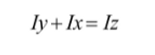
The area moment of inertia, Iz, is the sum of the moments of inertia about the X and Y axis, Ix and Iy can be generalized with the following equation:
When used to calculate the moment of inertia for a circular beam, specifically an Olympic barbell, the
equation becomes:
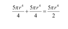
This equation shows how area moment of inertia varies with the radius of the beam, thus a thicker beam with a larger radius will give a higher area moment of inertia. This serves to explain why thicker objects tend to deform less when a load is added.
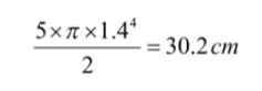
Using this equation, the area moment of inertia of a barbell with the above specified dimensions can be calculated to be:
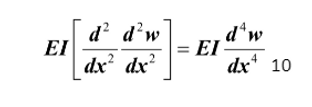
2.3 Euler Bernoulli beam equation
The Euler-Bernoulli beam equation is:

This is a general equation for static bending which is applicable to all types of beams and points of loading. This equation provides the means of calculating the load-carrying and deflection of beams, this includes calculating the deflection for Olympic barbells which are a type of beam.
However, from our previous calculations, holding the Elasticity Constant, E, and area moment of inertia, I, to be constant throughout the length of the barbell, we are able to simply this equation to:
Since E and I do not change with force applied or length, there is a positive correlation between displacement and force per unit length.
2.4 defining the symbols used for calculations

2.5 Deriving the relationship between flexion and force applied

A force is applied, p, causes a deformation in the bar which is similar to the lifter applying and upward force to lift a weight of 45kg, 450N, on either side of the bar. The points of support indicated by the triangles represent the points of contact of the weightlifting plates with the ground. The neutral axis is a horizontal line passing the center of the cross sectional area of the barbell, equal to the radius of the barbell.
Visual Representation

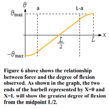
A graph may also be modeled after the flexion seen in the barbell.
The Y axis represents relative bending stress along the length of the barbell
The X axis represents the length of the barbell
The graph is derived from the equation:
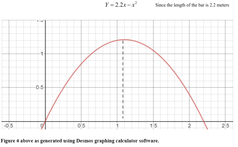
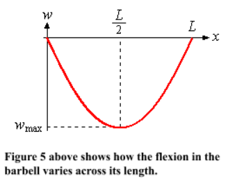
From the figure 5 it can be seen that the shape of the barbell is similar to that of a parabola with a maximum point. In this case the maximum point of the graph in figure 7 would be at X=1.1 at the center of the barbell where the barbell experiences the greatest relative bending stress. This graph runs in tandem with the graph in figure 5, showing that there is a direct positive correlation between bending stress and displacement in the barbell.
2.5.1 Displacement
The term Displacement here means the distance the bar deviates from its neutral position on the floor where no external forces act upon it.
Equations used to calculate displacement:
Given that x is the location along the beam where force p acts:

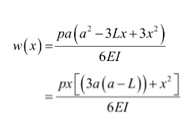
The reason the polynomial has to change is because the bending stress and Moments of a force that the barbell experiences vary along the length of the barbell, hence different polynomials need to be used to explain the forces that act within specific regions of the barbell.
From the graph it is observed that the center of the barbell experiences the greatest displacement as shown by the minimum point L/2.
By substituting x to be where w is wmax we would arrive at the final equation:

By subbing in a to be 40cm, L to be 220cm, P to be 900N and I to be 30.2cm4, we will be able to derive the max deformation in the bar by the following:

Therefore when a load of 900N is added to each side of the barbell, a flexion of 5cm can be observed in the barbell from its maximum point of flexion to normal state.
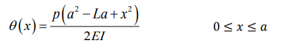
2.5.2 Slope/degree of flexion
Flexion here is seen as the gradient of the tangent drawn from the points along the barbell and is the measure of an angle. In this sense, the two ends of the barbell experience the greatest flexion as their tangent has the highest absolute gradient value.
The graph can be divided into three portions and their
respective equations may be derived. At the two ends where
x≤a and x≥L-a the graph is parabolic, suggesting that
flexion has reached its maximum points at the two ends.
The middle of the graph shows a linear trend line.
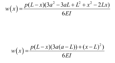
Thus knowing this the Equations used to calculate degree of
flexion can be derived:


The reason the two ends of the barbell show the greatest sloping is because they experience the greatest moment. Moment, also known as torque, is a product of force and distance from pivot, by taking the pivotal point to be the placement of the hands of the lifter near the middle of the bar at the point L/2, it is evident that the two extreme ends of the barbell would show the greatest flexion from the pivotal point as their moment arm is the greatest. Therefore from the graph, θmax can be determined by substituting x to be 0 and L into the above equations:

The two equations are combined to give us the final equation:
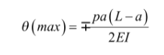
This is the general equation to calculate the maximal flexion of a beam at the ends. Since the parameters of the lift are already known, θmax can be deduced by simply substituting in the corresponding values of L, a, P and I. This would work out to be:

2.5.3 Moment and maximum bending stress
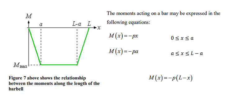
Hence from these 3 equations and with reference to figure 4, the Mmax can be derived with the following equation:

Which is the length of the moment arm, a, in meters multiplied by the downward force of the weights, p.
When these two values are subbed in, the Moment max is calculated to be:
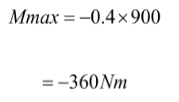
Figure 4 of the moments of a force experienced along the barbell corroborates with that of flexion in figure 3. Comparing the two graphs, one similarity that can be drawn is that at the point when the torque reaches its maximal the flexion trend line also becomes linear, and while torque increases, the degree of flexion seems to increase exponentially with reference to figure 3. This seems to show that the torque in a barbell influences the degree of flexion such that increasing the torque increases the rate of change in the degree of flexion observed.
Calculating maximum bending stress:
The equation for maximum bending stress can be derived from Mmax by the formula:
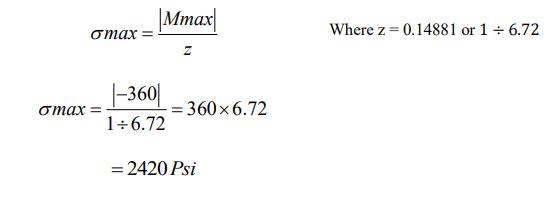
Therefore, from the calculations it can be seen that a force of 900N on either side of the barbell will create a bending stress of 2420 Psi at the “outer fibers” of the barbell.
The moment stress relationship can be represented by the equation for a straight line graph:
Y=6.72X
Where Y is bending stress and x is the moment
The gradient of the line is 6.72 and it intercepts the Y axis at the origin as c is 0.
3. Data collection & Processing
A dynamic 4 point bending stress test was carried out at Jurong LakeGardens ActiveSg gym, where instead of the weights being static and supported by two support structures, an actual deadlift movement was carried out on the barbell to create maximal flexion in the bar.
3.1 Methodology
A standard barbell with the specific dimensions was placed on a platform. 10kg weights were added on either side of the barbell. The weights were 2cm in length and of the same height as a regular 20kg weightlifting plate. A conventional deadlift pull was performed on the barbell. The maximum displacement (flexion) in the barbell during the initial “jerk” to lift the barbell was measured using a ruler
This was repeated several times, adding 10 kg on either side of the barbell from 10kg to 100kg. The resulted collected were tabulated in a table and a graph was plotted.
Note that during data collection, the weights were assumed to be of uniform density and of identical mass and dimensions
3.2 Raw data

3.3 Graphing

Discussion
The data collected supports the theoretical calculations, showing that a load of 900N, 90kg, on either side, totaling 200kg results in 4.83cm in deformation. This is approximately 0.17cm lesser than the theoretical deformation of 5cm. This can be explained by the assumption made during calculations that the barbell is completely made of cast iron. In reality the barbell is an alloy and is a mixture of several elements such as carbon making it stiffer thus leading to a lower flexion and deformation observed. The data collected is also similar to the values collected by other research papers done. Literature sources show that 1000N of weight loaded onto a static barbell gives a deformation of 4cm. This is slightly lower than the values collected for this investigation since a dynamic test was conducted in the force of a deadlift rather than static loading and unloading of weights in the research paper.
From graph 3.3, it is evident that flexion in a barbell is directly proportional to the force applied to it. This can be represented by the equation
By increasing the weight by 100N, a deformation of approximately 0.437cm and a flexion of 0.5o will be observed. The deformation can be attributed to the moment arm produced on either side which causes a bending stress at the center of the barbell, causing the extreme outer fibers to deform and bend.
Furthermore, it can be seen that the relationship is linear and does not increase exponentially with increasing amount of weight due to the elasticity of the barbell, allowing it to bend and still return to its original shape. However it is unclear for how long this trend continues as only 10 data points were collected. By referring to other research papers, this trend line does not hold for greater weights which exceed the stiffness of the barbell. Hence the actual force-flexion graph would be logarithmic and not linear when heavier and heavier weights are added and eventually will plateau as the bar would deform to a point where it can no longer return to its original shape. This is known as breaking stress which is equal to the yield strength of the material.
Evaluation
Strengths
During data collection, the same barbell was used for each replicate; this ensures that the deformation would be consistent as more weights were added. Furthermore, Rulers were used to measure the deformation of the bar from its neutral axis, allowing for precise measurements of up to ±0.1cm to be taken reducing the uncertainty during calculations. The weights used were calibrated bumper plates from Eleiko, hence ensuring their mass and dimensions are consistent and accurate.
Limitations
In real life context, the barbell would have been already used and exposed repeatedly to heavy weights overtime and hence are subject to wear and tear and being worn down. This decreases its flexural strength as the fibers within the barbell lose their tensile strength. Hence the deformation in the barbell would be more than when the barbell was newly made. Anecdotally, it is nearly impossible for a lifter to have the same starting position and exert the same force production for every lift. There will always be small variations in the force produced during the initial jerk due to random errors such as foot placement, hand placement and concentration at the point in time. This would cause deviations in the deformation of the barbell compared to a static stress test
Extension
For further research, I can expand this equation to apply to both the bench press and squat as well. By utilizing the same equations above, I would be able to calculate the bar flexion observed in a standard bench press and squat as well. Furthermore, I can also extend my research to find the correlation between Specific body proportions to a specific lift and how that affects their force production. For example, do shorter legs favor the squat or deadlift more?
The methodology described in this investigation can also be used to determine the mechanical properties of other barbells such as a calibrated powerlifting barbell used for powerlifting competitions and an elephant bar used in strongman competitions.
Practical application
Bar deformation is a natural phenomenon as a result of the physical properties such as elasticity and tensile strength of the barbell, the forces and stress that the bar is placed under during a lift causes it to bend and deform naturally. Anecdotally , Bars that provide greater flexion have greater “whip” and hence are easier to lift as they allow the weightlifter to utilize the natural leverages they have and pull the slack out of the bar, providing themselves more room to overcome the inertia of the weights. Olympic weightlifters for example time their lift to correlate with the upward oscillation of the weights when the bar is momentarily lighter to complete the lift. As such bars with greater stiffness are less viable for weightlifting exercises and also makes the deadlift harder.
Conclusion
Returning to the research question, it is apparent that there is a positive linear relationship between the force applied and degree of flexion measured in the barbell, with every additional 100N of force would produce a deformation of approximately 0.437cm with 0.5 degrees of flexion.
One clear finding of this paper is the force-flexion relationship of the barbell which can be represented by the equation:
This equation holds true to most of the weight which a person would realistically be able to lift in the gym. Due to the limited amount of space available on the collars for weight to be added and the density of the weights, only a finite amount of weight can be loaded and lifted using a standard Olympic barbell, hence for these practical purposes, this equation would hold true.
Bibliography:
-
Chiu, L. Z. F. (2010). Mechanical Properties of Weightlifting Bars. Journal of Strength and Conditioning Research, 24(9), 2390–2399. doi: 10.1519/jsc.0b013e3181ecd359
-
Bending. (2019, December 16). Retrieved January 2, 2020, from https://en.wikipedia.org/wiki/Bending#Dynamic_bending_of_beams.
-
Second moment of area. (2019, December 20). Retrieved January 2, 2020, from https://en.wikipedia.org/wiki/Second_moment_of_area.
-
Inc. (n.d.). Euler-Bernoulli Beam Equation. Retrieved January 2, 2020, from http://www.efunda.com/formulae/solid_mechanics/beams/theory.cfm.
-
Jones, A. Z. (2019, June 20). Formulas for Finding the Moment of Inertia. Retrieved January 2, 2020, from https://www.thoughtco.com/moment-of-inertia-formulas-2698806.
-
Barbell. (2009, April 9). Retrieved January 2, 2020, from https://en.wikipedia.org/wiki/Barbell.
-
YOUNG'S MODULUS OF CAST IRON. (n.d.). Retrieved January 2, 2020, from https://www.amesweb.info/Materials/Youngs-Modulus-of-Iron.aspx.Toro, S. A., Aranda, P. M., García-Herrera, C. M., & Celentano, D. J. (2019). Analysis of the Elastoplastic Response in the Torsion Test Applied to a Cylindrical Sample. Materials, 12(19), 3200. doi: 10.3390/ma12193200